
Electrical design from point to board diagram
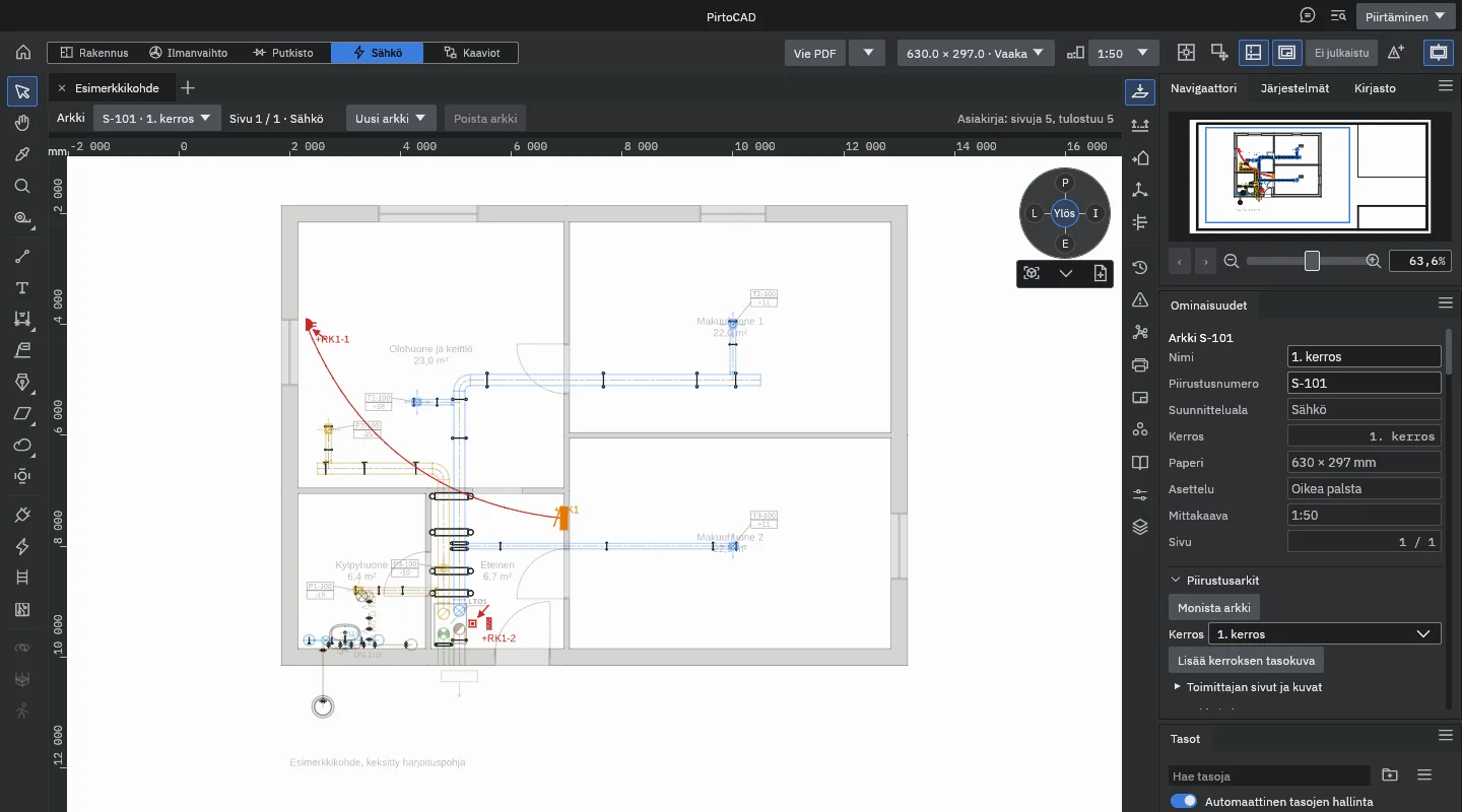
Electrical points, distribution boards, final circuits and wiring are drawn in the same model as the building and the ventilation. The Problems panel flags an overloaded circuit and a point on no circuit, and the electrical diagrams are generated from the model.
What you draw and check
Electrical points and boards
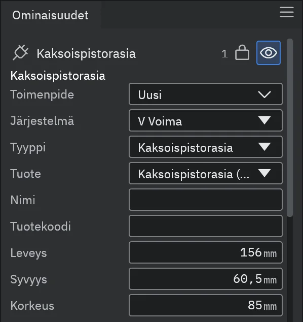
Choose the system in the options bar (power, lighting, telecom or fire alarm) and the point type, then click to place the points. The type list covers what Finnish electrical drawings use, from socket outlets and switches to downlights, LED strips and car heating outlets. A distribution board takes the next free code: RK1, RK2 and so on.
- A mounting height above the floor for every point, the top edge height for a board
- Rated power and switching group letter in the point's properties, plus a position code for fixed luminaires and electric heaters
Circuits, wiring and cable routes
Create a circuit on a board, give it a circuit description and a protective device such as C16, and put points on it. The board's circuit schedule adds up the points' power, and the circuit mark, for example +RK1-3, shows on the drawing. A wire is drawn from point to point, and its properties take the cable type and the phase conductor marks. A wire that continues to another storey gets an arrow.
A cable route is drawn as cable tray, cable ladder, conduit, trunking or buried cable, with a width, a height and a centre level.
Cable routes do not yet move with the objects around them, so draw them last.
Problems and fixes
The Problems panel checks the electrical points, circuits and switches on the active storey. Clicking a row selects the point or the circuit's points. The fix is in the context menu of the point or switch, and a fix that concerns a circuit carries the circuit number in its name, as below.
- A circuit whose current exceeds the rated current of its protective device (a 4 kW load on a C10 circuit draws 17.4 A): fix Split circuit 1 in two, when the circuit has at least two points
- An electrical point on no circuit: fix Put on circuit 1, which puts the point on the circuit of the nearest point that has one
- A switch that switches nothing: fix Link to the nearest luminaire
- An air handling unit, motorised damper, actuated fire damper or pump with no supply point: fix with the Add HVAC supply points button in the Problems panel
Diagrams, legends and schedules
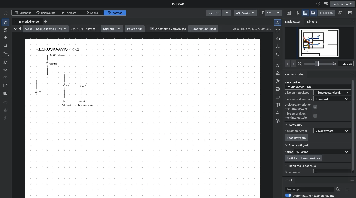
When you create a new sheet of the type Electrical diagram in the Diagrams discipline, the electrical model generates a main distribution diagram, a board diagram, a circuit diagram, a board front arrangement or a telecom and antenna diagram. After the model changes, generating the diagram again updates the generated objects and keeps the ones you added yourself.
- A legend row on the sheet for every electrical symbol used
- Luminaire schedule by position code, with power and quantities
- Mounting height on the drawing in the form h 1800
Checks and their basis
Hover over a row in the Problems panel to see its details, for example the circuit current and the rated current of the protective device. The table shows what each electrical check is based on.
| Check | Basis | Where it shows |
|---|---|---|
| Circuit load | The circuit's design current compared with the rated current of the protective device; a C10 device is rated 10 A. The design current is either a current typed for the circuit or is calculated from the points' power. | Problems panel, point context menu |
| Smoke alarm less than 2 m from a supply air terminal | The distance given in a smoke alarm manufacturer's Finnish instructions | Problems panel, point context menu |
| Warning tape depth of a buried cable, 200-400 mm | The lower limit comes from a distribution network operator's public connection guide. The upper limit is the value used in Finnish drawing sets and has not been verified. | Cable route properties, Problems panel |
| Supply point for HVAC equipment | The project's air handling units, motorised dampers, actuated fire dampers and pumps. Voltage and power come from the product data, and missing data is never guessed. | Problems panel |
The designer is responsible for the results. The window does not yet calculate voltage drop or fault current. An empty Problems panel means that the program's current checks found nothing. It does not mean that the design has been checked or that it complies with regulations.
Coming to electrical design
These are not in the window yet. Items marked (command) already run as commands of pirtocad-cli and the MCP server, for example from an AI agent.
- Residual current device, cable type and phases editable in the circuit's details (command)
- Circuit check: design current, cable current-carrying capacity and protective device (command)
- Cable sizing from the circuit check (command)
- Voltage drop and minimum fault current at the end of the circuit (command)
- Switch legend table
- Cable routes that move with the objects around them
The electrical designer's path
The planned path is the foundations course first, then the electrical course, which moves from a one-storey house to a two-storey house and a terraced house. No episodes have been published yet.
 Video coming